公告版位
Bewise Inc. www.tool-tool.com Reference source from the internet.

焼なましとは、鋼の結晶粒度を調整し、軟らかくする操作で、その目的によって種々な方法があります。いずれの場合も、

①A又はA3-1変態点以上+50℃に加熱し、完全にオーステナイト化させます。

②Ar点直下(約700℃)でオーステナイトをパーライトに変態させます。

(1)完全焼なまし

一般的に焼なましと云えば、この完全焼なましのことを云います。変態点以上+50℃

の温度に加熱した後、約25~40℃/h以下の温度で炉冷します。冷やし方は炉冷ですが、室温までゆっくりと冷やす必要はありません。臨界区域(約550℃)位まで炉冷したら、炉から取り出し後が空冷で良いのです。ただし、残留応力を嫌う場合は、400℃位まで徐冷すると良いでしょう。

(2)等温焼なまし

等温冷却を利用する方法です。TA温度から約600℃(S曲線の鼻より高い温度)に保った等温炉に入れ、等温変態が終了した後、取り出して空冷します。この処理は短時間で操作が完了でき、また、炉の循環的な利用も可能です。

(3)球状化焼なまし

パーライト中のセメンタイトを又は網状セメンタイトを球状化させるための焼なましです。球状化の方法には、

①Ac点直下又は直上の温度に長時間加熱した後、ゆっくり冷やす方法。

②Ac点の直上まで加熱し、Ar点直下まで冷却を数回繰返し行う方法。

③簡単に球状化したい場合、また、構造用鋼など球状化がし難い鋼は、一度焼入れを行い、高温(650~700℃)で焼戻しを行うと比較的球状化が容易にできます。

(4)応力除去焼なまし

冷間鍛造や圧延、溶接、鋳造品などの残留応力を除去し、軟化させたり、ひずみを少なくするための処理で、一種の低温焼なましです。加熱温度は鋼の再結晶温度(約450℃)以上、A変態点以下の温度です。通常は550~650℃が多く用いられています。冷却は徐冷(炉冷)が良いが、450℃以下は空冷でも効果的です。また、焼入変形を少なくするための前処理としての効果もあります。

金属組織について(2)

一般的な熱処理についてお話をしましたので、それらの処理によって生じた金属組織について、前に記述しなかった組織を概略解説しましょう。

スッテダイト

りん化鉄(FeP)と含りんオーステナイトの共晶を云います。熱処理では直接関係がありませんので省きましたが、片状黒鉛鋳鉄中の含りん共晶は、このスッテダイトです。また、Pを多く含む炭素鋼にも現れることがあります。

レデブライト

鉄鋼材料を融液から冷却してくると、1148℃でオーステナイトとセメンタイトが同時に晶出します。この共晶をレデブライト又はウエストと呼んでいます。レデブライトのC量は4.3%です。

複炭化物

FeとC、Mo、W、V、Crなど2種類以上の元素が化合してできた金属間化合物を複炭化物と云います。ダイス鋼(SKD)や高速度鋼(SKH)などの高合金鋼に多く存在する炭化物で、MC、MC、M23などがあります。Mは(FeCr)、(FeMo)など添加した金属元素を表します。

繊維状組織

冷 間で加工し塑性変形を与えれば、結晶粒は加工方向に繊維状に伸び、加工度が大きくなると結晶粒は繊維を束ねたような組織にあります。このように加工方向に 伸びた組織を繊維状組織と云います。この組織は、伸びた方向と直角方向では強度がかなり違います。このような組織は再結晶温度以上に加熱すれば元に戻りま す。

トルースタイト

焼入れによって得られたマルテンサイトは、α鉄に多量のCが固溶したもので、硬くてもろい性質があります。これを粘い性質にするために、Cを吐き出させる必要があります。約400℃に加熱(焼戻し)すると、硬いマルテンサイトからFeCの形でCを吐き出します。この組織がトルースタイトです。フェライトとセメンタイトの混合組織で、マルテンサイトに次ぐ硬さです。ばね性もありますが、さびやすいのが欠点です。フランスのトルーストによって発見されました。硬さは400HV程度です。

ソルバイト

この組織もフェライトとセメンタイトの混合組織です。マルテンサイトをトルースタイトよりもさらに高い温度(550~650℃)で焼戻しをすると得られます。FeCがやや粗大化し、トルースタイトよりもさらに凝集した模様を呈します。軟らかくショックに強いため、じん性が要求される機械部品に多用されています。また、窒化や高周波焼入れの前処理として施されます。イギリスのソルビーが命名したもので、硬さは270HV位です。

ベイナイト

オー ステナイト化した鋼を焼入れする際、Ar′変態とAr″変態の中間の温度で等温処理すると、得られる独特な組織です。等温処理温度が高い (450~550℃)場合は、黒色の羽毛状(パーライトに近い)の組織が、また、比較的Ms点に近い温度で処理すると、針状(マルテンサイトに近い)の組 織となります。羽毛状を上部ベイナイト、針状を下部ベイナイトと云います。いずれのベイナイトも、硬さが同一ならば通常の焼入れ・焼戻し材よりも粘り強い 性質を持っています。米国のベインが発見したのでこの名前が付いています。

表面改質熱処理

前述したごとくバルク材の表面も内部も同時に、目的とする特性に変える処理を一般熱処理と呼びましたが、ここでは表面のみを改質する熱処理、特に表面硬化熱処理について概略解説しましょう。

表面硬化の種類

表 面硬化処理には物理的硬化法と化学的硬化法の2つがあります。物理的な硬化法は、表面の化学成分を変えることなく、焼入れだけで硬くする方法です。高周波 焼入れ、炎焼入れ、レーザ焼入れなどがあります。化学的な方法は、表面の化学組成を変えて、硬化させる方法で浸炭、窒化、浸硫窒化、ボロナイジング、拡散 浸透処理などがこれに該当します。いずれの場合も表面を硬くし、耐摩耗性、耐疲労性、耐食性、耐熱性などの向上が目的ですが、これらの処理のどれを選ぶか は、母材との兼ね合いもあって大切な問題の一つです。

物理的硬化法

高周波焼入れ(JIS記号HQI)

高 周波誘導加熱によって鋼を焼入れする場合、コイルと被加熱物に流れる電流は、周波数が高くなるにしたがい、それぞれの表面に集中してくる性質があります。 この現象を表皮効果と呼んでいます。コイルと被加熱物に流れる電流は、向きが互いに反対方向であり、周波数が高くなるとこの表皮効果によって、反対方向の 電流がますます接近して流れるので電気抵抗が少なくなります。被加熱物の表面のみが発熱するのはそのためです。電流の流れる表面の深さ(d)と周波数 (f)との間には、次のような関係式があります。

d=5.03×10√ρ/(μ・f)

ただし、d:透過深さ(cm)、ρ:固有抵抗(μΩ・cm)、f:周波数、(Hz/sec)、

μ:透磁率

つまり、簡単に云えば電流の周波数が高くなるほど、加熱深さが浅くなります。例えば周波数10KHzの時は焼入れ深さは5mmとなります。表15に高周波発生装置の種類と特徴を示しましたが、現在では周波数の範囲が広い、サイリスタインバータ式の発振機が多用されています。高周波焼入れの特徴は、

(1)直接加熱ですから熱効率が良く、作業時間が短い。

(2)局所焼入れが可能で、硬化層深さの選定も比較的容易である。

(3)短時間加熱、急冷処理のため酸化、脱炭、変形が少ない。

(4)作業の標準化、自動化が容易である。

(5)急熱、急冷のため表面に大きな圧縮残留応力が生じ、耐摩耗性のみならず耐疲  労性も向上する

などが挙げられます。

高周波焼入加熱は、コイルによって行われますので、被加工品の寸法、形状に適したコイルの作成が重要です。コイルの種類には外面用、内面用、平面用などがありますが、コイルの選定は経験的な要素が多々あります。

高周波焼入れは、一般的に機械構造用炭素鋼及び低合金鋼が多く用いられていますが、急速加熱のため、炭化物が十分固溶しない内に温度が上昇し、Ac変 態点は鉄-炭素系状態図の場合よりも若干高くなります。したがって、高周波焼入れ硬さは、焼入れ前の素地組織によって大きく影響されます。ソルバイト組織 のものは炭化物が十分に固溶しますので、焼入れ硬さは高くなります。硬さの表示は有効硬化層深さと全硬化層深さの2つがあります。有効硬化層深さは50% マルテンサイト(これをハーフマルテンと呼んでいます)までの深さに該当し、鋼のC%によってその限界硬さが決められています。また、全硬化層深さは母材 の硬さまでの深さを採用しています。

冷却剤は水溶性冷却液が一般的に多く用いられ、冷却方法は大きな冷却速度が得られる噴射式が多用され、クランクシャフト、歯車、カム、ロール、シリンダライナなどに施されています。

炎焼入れ(JIS記号HQF)

ア セチレンガス、都市ガス、プロパンガスなどと酸素との火炎によって、鋼の表面のみを加熱し、焼入れする操作です。高周波の場合は誘導電流によって自己発熱 する内熱式に対し、炎の場合は外熱式です。いずれにしても耐摩耗性や耐疲労性の向上を目的とした処理です。特徴としては、

(1)被処理品の形状や寸法に制限を受けない。

(2)局所焼入れが可能で、硬化層深さの選定も比較的容易である。

(3)急速加熱、冷却のため酸化、脱炭、変形が比較的少ない。

(4)肉薄部品の局所焼入れは不向きである。

などが挙げられます。

焼 入れ用の炎は、中性炎を用い最高温度の部分を利用します。また、高周波焼入れのコイルと同様に、炎焼入れにおいては火口の設計が重要なポイントです。火口 は燃料ガスの種類や被加熱物の形状、大きさ、焼入れ硬化深さなど目的によって設計が変わり、ガスと酸素の混合形式から、元混合形、先混合形に、また、炎の 形成上から孔及びスリットがあります。なお、用いる鋼は高周波焼入れの場合と同じであり、有効硬化層深さも同じと考えて良く前表を採用しています。また、 表面硬さは大体次式によって推定ができます。

HRC=15+C Cは(%×100を表します)

高周波の場合も同様ですが、焼入れした後は必ず焼戻しを行います。

レーザ焼入れ

レー ザ焼入れは、高エネルギー密度のレーザビームを鋼部品の表面に照射して加熱し、自己冷却作用によって焼入硬化させる方法です。レーザ発振装置には炭酸ガス レーザ、YGレーザ、プラズマレーザ、エキシマレーザなど色々ありますが、焼入れに用いているのは、炭酸ガスレーザが多いようです。レーザビームによる加 熱は超急速であり、また、焼入れも冷却剤は用いず自己冷却です。したがって、短時間に小さい面積で局所焼入れができ、ひずみの発生も少ない利点がありま す。一般的に焼入れ後は焼戻しを行いません。

電子ビーム焼入れ

電 子ビーム焼入れは、真空中で電子ビームを被処理物の表面上を走らせながら加熱し、自己冷却によって焼入れる方法です。真空を用いる不便さはありますが、酸 化や脱炭などが無く良好な結果が得られます。また、比較的熱効率も良く、今後機械部品の小局所表面焼入硬化に多用されることと思います。

化学的硬化法

浸炭(JIS記号HC)

低炭素鋼(通常肌焼鋼と云っています)の表面にCを浸透拡散させ、高炭素としたのち、これを焼入れして表面を硬くする方法を浸炭と呼んでいます。浸炭焼入れには固体浸炭、液体浸炭、ガス浸炭の3種類がありますが、色々な理由から現状ではガス浸炭焼入れが主流です。表17は各種の方法について特徴を示したものです。いずれの場合も、表面が硬く内部が軟らかいため、耐摩耗性、耐疲労性に優れています。使用鋼は一般的に低炭素鋼が用いられ、次のような条件を満たしていることが必要です。

(1)浸炭温度に加熱した際、結晶粒の粗大化を起こさないこと。

(2)硬化層の硬さが高く、耐摩耗、耐疲労、高じん性を有すること。

(3)内部の被硬化部においても、結晶粒が粗大化せず、高じん性を有すること。

(4)浸炭を阻害する元素が少なく、遊離の炭化物を作る元素が含まれていないこと。

(5)加工性が良く、価額も安いことなどが挙げられます。

固体浸炭(HCS)

固 体浸炭は、浸炭箱に処理品と木炭を主成分とした浸炭剤を積め、ふたで密閉をして行う処理です。この方法は各種の浸炭法の中で最も歴史が古く、炉の設備や作 業法も簡単ですが、常に品質を一定に保つことが難しく、また、作業環境も悪いことから現在ではあまり行われていません。浸炭機構は基本的には、ガス浸炭の 場合と同じです。箱内に詰められた浸炭剤は箱内に存在する酸素と反応し、炭酸ガス(CO)となり、さらにCOは炭素と反応して、一酸化炭素(CO)となります。

C+O→CO

C+CO⇔2CO

このCが鋼の表面で分解して(C)となります。この(C)は通常のCと異なり、活性化炭素と云っています。実際には

          Fe+2CO→[Fe-C]+CO

によって浸炭が行われます。

液体浸炭(HCL)

青 酸カリ、青酸ソーダなど青化物を主成分とする塩浴を用い、約900℃に加熱した浴中に処理品を浸漬して浸炭します。浸炭層のコントロールは処理時間と温度 によって行い、低温で短時間の場合は薄い浸炭層が、また、高温で長時間になると厚い浸炭層が得られます。しかしながら、シアン公害の問題から最近では斜陽 傾向にあり、シアンを含まない液体浸炭も開発されています。

ガス浸炭(HCG)

天 然ガス、都市ガス、プロパン、ブタンガスなど変成した浸炭性ガスあるいは液体を滴下し発生した浸炭性ガス中で処理品を加熱し、浸炭を行う方法です。ガス浸 炭には一般的なガス浸炭の他真空炉を用いた真空浸炭、プラズマを利用したプラズマ浸炭(イオン浸炭とも云っています)、また、メタノールなどの液体を浸炭 炉内に滴下し、その分解ガスによって浸炭を行う滴注式浸炭法などがあります。現在では特別な場合を除き、品質管理、生産性、公害などの観点から、このガス 浸炭法が汎用されています。浸炭機構は固体浸炭の場合と同様です。ガス浸炭処理で最も留意すべき点は粒界酸化の問題です。できるだけ粒界酸化を防ぎ、ま た、残留オーステナイトの生成を抑えることが大切です。従来の浸炭は表面の炭素濃度を共析組成(0.78%)とし、焼入れによって得られたマルテンサイト により耐摩耗性の改善を図っていましたが、この状態では、摩擦熱による温度上昇や高い温度雰囲気中で使用する場合などは、軟化現象が生じ寿命が低下するこ とがあります。このような現象を防止する目的から、表面近傍の炭素濃度を3%前後まで上昇させ、球状化して分散させた炭化物分散浸炭なども行われていま す。

浸炭窒化

浸 炭と同時に窒化処理も行う方法です。古くは青酸ナトリウム(NaCN)や青酸カリ(KCN)を主成分とする塩浴を用い、750~850℃で処理していたも のが、これに相当し液体浸炭窒化と呼ばれていました。シアンを用いるこの方法も、前述のシアン公害の問題から斜陽傾向にあります。しかしながら、ガスによ る浸炭窒化の場合は、比較的焼入性の低い材料に適用でき、若干残留オーステナイトが生成し易いが、通常浸炭よりも低温で処理が可能なため、利用頻度が多く なってきています。この処理法は通常のガス浸炭性ガス雰囲気中に0.5~1.0%のアンモニア(NH)を添加し850℃前後の温度で行います。

窒化処理

窒化処理は鋼の表面に活性化窒素(N)を浸透させて、表面を硬くする方法です。鋼の表面にNが入ると表18のような窒化物を作ります。この窒化物は非常に硬いため、処理状態で用います。したがって、浸炭のような焼入れ操作は必要としません。処理温度はA変 態点以下のα-Fe区域(510~570℃)です。処理温度が低いため焼割れや焼ひずみの心配もありません。鋼中に入るNはアンモニアなどが熱分解してで きた発生期のNが必要で、この窒素と親和力の強いAl、Cr、Moなどが鋼中に存在していることが重要です。特にCr、Moは不可欠成分です。JISで規 定されているSACM645はAl、Cr、Moが含まれている窒化専用鋼です。もちろんSCMやSKDなども窒化処理を行って用いています。

表面に生成される窒素化合物は前述したFeN、Fe2-3N、FeNであり、白層と呼ばれている最表面の相はFe2-3Nです。いずれにしても、調質をしてから窒化処理をするのが基本です。なお、窒化防止にはSnめっき又はNiめっきなど行います、これをマスキングと云っています。

窒化硬化層深さには全硬化層深さと実用硬化層深さの二つがあります。全硬化層深さは測定が困難なため、母材の硬さよりも50HV高い、実用硬化層深さのほうが良く採用されています。

ガス窒化(HNTG)

1923 年、A.Fryによってアンモニアの分解ガスを用いたのが最初です。500~550℃に加熱したアンモニア分解ガス中で、50~150時間処理します。こ の時のアンモニアの分解率は30%前後にします。この処理によって深さ0.2~0.3mm、1000~1200HVの硬さが得られます。耐摩耗性、耐食性 に優れた特性が得られますが、処理時間の長いのが欠点です。

プラズマ窒化(イオン窒化)

窒化時間の長いのを補う目的で開発されたのがプラズマ窒化です。イオン窒化とも呼んでいます。この処理は低減圧の真空中により、放電によって行うガス窒化の一種です。図36に 示すごとく、処理物を陰極、容器を陽極とし0.5~10Torrの真空中で約500Vの電圧をかけ放電を行います。この時アンモニアを導入すると窒化が行 われるのです。窒化時間は数時間で良く、ガスも節約でき公害もありません。また、処理温度は450~570℃です。処理雰囲気には窒素と水素の混合ガスが 多く用いられています。

塩浴軟窒化(HNTT)

塩 浴軟窒化の代表的な処理はタフトライドです。この処理は青酸カリや炭酸カリなどをチタンるつぼに入れて溶融し、この中に空気を吹き込みながら処理を行う方 法です。処理温度は570℃前後、時間は30~240分程度、加熱後は油冷か水冷を行います。用いられる鋼はオールマイティと云っても過言ではない位全て の材料に適しています。ただ、シアンの問題があり、最近ではシアン公害をゼロにした処理も開発されています。ガス窒化やプラズマ窒化と大きく異なる点は、 後述するガス軟窒化と同様に、窒素と炭素が同時に侵入し、炭窒化物が形成されることです。写真14は塩浴軟窒化処理鋼の一例です。

浸硫窒化

窒 素と硫黄を同時に侵入拡散させる処理です。塩浴軟窒化性浴の中に硫黄化合物を添加し、窒素化合物と硫黄化合物を同時に鋼表面に生成させる方法です。この処 理には高濃度のものと低濃度の処理があり、また、比較的低温で行う電解浸硫窒化処理も行われています。いずれの場合も耐摩耗性と耐焼付き性が改善されま す。

ガス軟窒化

軟窒化をガスによって行う方法で、公害は全くありません。この処理にはアンモニアガスと浸炭性ガスを混合して使う場合と、尿素を分解して用いる方法とがあります。

アンモニアガスと浸炭性ガスを1:1の割合で混合して用いる軟窒化は、ガス軟窒化の主流です。この他窒素ガスベースのものもあります。また、尿素の熱分解で生じたCOとNで軟窒化を行う方法もあります。処理温度や時間は他の軟窒化法と同じです。写真15は金属組織であり、表面の白層がε窒化物(Fe2-3N)です。

ボロナイジング(ほう化処理)

鋼の表面にFeB(約2000HV)、FeB (約1600HV)のボロン化合物を生成させ、これらの持つ高い硬さ値と非金属的物性によって耐摩耗性、耐焼付き性の改善を図る処理をボロナイジング又は ほう化処理と呼んでいます。処理方法には固体、液体、気体の3通りがあります。いずれも日本では余り行われていませんが、ヨーロッパでは耐摩耗部品や金型 類に汎用されています。最表面には処理方法と条件によって異なりますが、反応生成物としてFeB、FeBが生成されます。耐摩耗性の観点からはFeB単相の方が好ましいです。処理温度は1000℃前後の高温で行われるため、ひずみの発生があります。これらを考慮して処理することが大切です。

炭化物被覆処理

炭 化物被覆処理法にはPVD(物理的蒸着法)やCVD(化学的蒸着法)のようなドライコーティング、TRD(VC炭化物コーティング)のようなウエットコー ティングの2通りがあります。いずれの場合も鋼表面に硬い炭化物あるいは窒化物を生成させる方法です。PVDやCVDには色々な方法があり、硬質皮膜も TiN、TiC、TiCN、TiAlNなど、また、硬質皮膜のみならず光学的、物理的皮膜が種々検討され、すでに実用化されている皮膜も少なくありませ ん。また、TRDは表面に硬いVC炭化物を生成させるもので、すでに実用化され金型など広範囲で使用されています。この処理は、素地と炭化物層の相互拡散 によって密着強さが高く、はく離を起こし難い特徴がありますが、高温処理のため大きなひずみが発生しやすく、この問題解決にはある程度の経験が必要です。 なお、最近ではα区域の低温で炭窒化物被覆する方法も開発されています。

水蒸気処理(ホモ処理)

鉄には一酸化鉄(FeO)、三酸化鉄(Fe)、四酸化鉄(Fe)の3種類の酸化鉄があります。FeOは白さび、Feは赤さび、Feは黒さびと云われています。Feは多孔質で硬く、耐食性に富んでいるので表面改質に利用されます。この膜を作るのには水蒸気を用います。赤さびが生じないように、加圧水蒸気を350~400℃に予熱した後、500℃前後に加熱した過熱水蒸気を処理品に通じるとFe膜ができます。温度が高すぎたり、時間が長すぎたりするとFeはFeに変化してしまいますので注意をして下さい。ます。

歡迎來到Bewise Inc.的世界,首先恭喜您來到這接受新的資訊讓產業更有競爭力,我們是提供專業刀具製造商,應對客戶高品質的刀具需求,我們可以協助客戶滿足您對產業的不同要求,我們有能力達到非常卓越的客戶需求品質,這是現有相關技術無法比擬的,我們成功的滿足了各行各業的要求,包括:精密HSS DIN切削刀具協助客戶設計刀具流程DIN or JIS 鎢鋼切削刀具設計NAS986 NAS965 NAS897 NAS937orNAS907 航太切削刀具,NAS航太刀具設計超高硬度的切削刀具BW捨棄式鑽石V卡刀BW捨棄式金屬圓鋸片木工捨棄式金屬圓鋸片PCD木工圓鋸片醫療配件刀具設計汽車業刀具設計電子產業鑽石刀具全鎢鋼V卡刀-電路版專用全鎢鋼鋸片焊刃式側銑刀焊刃式千鳥側銑刀焊刃式T型銑刀焊刃式千鳥T型銑刀焊刃式螺旋機械鉸刀全鎢鋼斜邊刀電路版專用鎢鋼焊刃式高速鉸刀超微粒鎢鋼機械鉸刀超微粒鎢鋼定點鑽焊刃式帶柄角度銑刀焊刃式螺旋立銑刀焊刃式帶柄倒角銑刀焊刃式角度銑刀焊刃式筒型平面銑刀木工產業鑽石刀具等等。我們的產品涵蓋了從民生刀具到工業級的刀具設計;從微細刀具到大型刀具;從小型生產到大型量產;全自動整合;我們的技術可提供您連續生產的效能,我們整體的服務及卓越的技術,恭迎您親自體驗!!

BW Bewise Inc. Willy Chen willy@tool-tool.com bw@tool-tool.com www.tool-tool.com skype:willy_chen_bw mobile:0937-618-190 Head &Administration Office No.13,Shiang Shang 2nd St., West Chiu Taichung,Taiwan 40356 http://www.tool-tool..com / FAX:+886 4 2471 4839 N.Branch 5F,No.460,Fu Shin North Rd.,Taipei,Taiwan S.Branch No.24,Sec.1,Chia Pu East Rd.,Taipao City,Chiayi Hsien,Taiwan

Welcome to BW tool world! We are an experienced tool maker specialized in cutting tools. We focus on what you need and endeavor to research the best cutter to satisfy users demand. Our customers involve wide range of industries, like mold & die, aerospace, electronic, machinery, etc. We are professional expert in cutting field. We would like to solve every problem from you. Please feel free to contact us, its our pleasure to serve for you. BW product including: cutting toolaerospace tool .HSS DIN Cutting toolCarbide end millsCarbide cutting tool

beeway 發表在 痞客邦 留言(0) 人氣()


Bewise Inc. www.tool-tool.com Reference source from the internet.

正火和淬火的加热温度及保温时间都是及其相近的,不同的是淬火后,经回火可达到调质的目的,但是正火后,其机械性能肯定也有提高,请问大虾和调质处理的,差异有多少呢。
如果同样的钢种直接回火的话,和正火处理的又有什么差别呢。

现在处理的是美国钢级J55,成分为 37Mn5,一般是用来调质处理的,即是将J55钢级调质为N80,各项机械性能都有了较大的提高,但我们现在是只正火,其各项性能指标是否是应该介于J55和N80之间的。

正火是一种低成本的热处理方案。
将亚共析碳钢加热到Ac3以上30~50℃,过共析碳钢加热到Accm以上30~50℃,保温,空气中冷却的方法称为正火。
适用于碳素钢及中、低合金钢,因为高合金钢的奥氏体非常稳定,即使在空气中冷却也会获得马氏体组织。对于低碳钢、低碳低合金钢,细化晶粒,提高硬度(140~190HBS),改善切削加工性能;对于过共析钢,消除二次网状渗碳体,有利于球化退火的进行。


1.钢的退火
退火是生产中常用的预备热处理工艺。大部分机器零件及工、模具的毛坯经退火后,可消除铸、锻及焊件的内应力与成分的组织不均匀性;能改善和调整钢的力学性能,为下道工序作好组织准备。对性能要求不高、不太重要的零件及一些普通铸件、焊件,退火可作为最终热处理。
钢的退火是把钢加热到适当温度,保温一定时间,然后缓慢冷却,以获得接近平衡组织的热处理工艺。退火的目的在于均匀化学成分、改善机械性能及工艺性能、消除或减少内应力并为零件最终热处理作好组织准备。
钢 的退火工艺种类颇多,按加热温度可分为两大类:一类是在临界温度(Ac3或Ac1)以上的退火,也称为相变重结晶退火。包括完全退火、不完全退 火、等温退火、球化退火和扩散退火等;另一类是在临界温度(Ac1)以下的退火,也称低温退火。包括再结晶退火、去应力和去氢退火等。按冷却方式可分为连 续冷却退火及等温退火等。
2.钢的淬火与回火
钢的淬火与回火是热处理工艺中很重要的、应用非常广泛的工序。淬火能显著提高钢的强度和硬度。如果再配以不同温度的回火,即可消除(或减轻)淬火内应力,又能得到强度、硬度和韧性的配合,满足不同的要求。所以,淬火和回火是密不可分的两道热处理工艺。
2.1 钢的淬火
淬火是将钢加热到临界点以上,保温后以大于临界冷却速度(Vc)冷却,以得到马氏体或下贝氏体组织的热处理工艺。
2.2 钢的回火
回火是将淬火钢加热至A1点以下某一温度保温一定时间后,以适当方式冷到室温的热处理工艺。它是紧接淬火的下道热处理工序,同时决定了钢在使用状态下的组织和性能,关系着工件的使用寿命,故是关键工序。
回火的主要目的是减少或消除淬火应力;保证相应的组织转变,使工件尺寸和性能稳定;提高钢的热性和塑性,选择不同的回火温度,获得硬度、强度、塑性或韧性的适当配合,以满足不同工件的性能要求。

歡迎來到Bewise Inc.的世界,首先恭喜您來到這接受新的資訊讓產業更有競爭力,我們是提供專業刀具製造商,應對客戶高品質的刀具需求,我們可以協助客戶滿足您對產業的不同要求,我們有能力達到非常卓越的客戶需求品質,這是現有相關技術無法比擬的,我們成功的滿足了各行各業的要求,包括:精密HSS DIN切削刀具協助客戶設計刀具流程DIN or JIS 鎢鋼切削刀具設計NAS986 NAS965 NAS897 NAS937orNAS907 航太切削刀具,NAS航太刀具設計超高硬度的切削刀具BW捨棄式鑽石V卡刀BW捨棄式金屬圓鋸片木工捨棄式金屬圓鋸片PCD木工圓鋸片醫療配件刀具設計汽車業刀具設計電子產業鑽石刀具全鎢鋼V卡刀-電路版專用全鎢鋼鋸片焊刃式側銑刀焊刃式千鳥側銑刀焊刃式T型銑刀焊刃式千鳥T型銑刀焊刃式螺旋機械鉸刀全鎢鋼斜邊刀電路版專用鎢鋼焊刃式高速鉸刀超微粒鎢鋼機械鉸刀超微粒鎢鋼定點鑽焊刃式帶柄角度銑刀焊刃式螺旋立銑刀焊刃式帶柄倒角銑刀焊刃式角度銑刀焊刃式筒型平面銑刀木工產業鑽石刀具等等。我們的產品涵蓋了從民生刀具到工業級的刀具設計;從微細刀具到大型刀具;從小型生產到大型量產;全自動整合;我們的技術可提供您連續生產的效能,我們整體的服務及卓越的技術,恭迎您親自體驗!!

BW Bewise Inc. Willy Chen willy@tool-tool.com bw@tool-tool.com www.tool-tool.com skype:willy_chen_bw mobile:0937-618-190 Head &Administration Office No.13,Shiang Shang 2nd St., West Chiu Taichung,Taiwan 40356 http://www.tool-tool..com / FAX:+886 4 2471 4839 N.Branch 5F,No.460,Fu Shin North Rd.,Taipei,Taiwan S.Branch No.24,Sec.1,Chia Pu East Rd.,Taipao City,Chiayi Hsien,Taiwan

Welcome to BW tool world! We are an experienced tool maker specialized in cutting tools. We focus on what you need and endeavor to research the best cutter to satisfy users demand. Our customers involve wide range of industries, like mold & die, aerospace, electronic, machinery, etc. We are professional expert in cutting field. We would like to solve every problem from you. Please feel free to contact us, its our pleasure to serve for you. BW product including: cutting toolaerospace tool .HSS DIN Cutting toolCarbide end millsCarbide cutting toolNAS Cutting toolNAS986 NAS965 NAS897 NAS937orNAS907 Cutting Tools,Carbide end milldisc milling cutter,Aerospace cutting toolhss drillФрезерыCarbide drillHigh speed steelMilling cutterCVDD(Chemical Vapor Deposition Diamond )’PCBN (Polycrystalline Cubic Boron Nitride) Core drillTapered end millsCVD Diamond Tools Inserts’PCD Edge-Beveling Cutter(Golden FingerEdge modifying knifeSolid carbide saw blade-V typeV-type locking-special use for PC boardMetal Slitting SawaCarbide Side milling CuttersCarbide Side Milling Cutters With Staggered TeethCarbide T-Slot Milling CuttersCarbide T-Slot Milling Cutters With Staggered TeethCarbide Machine ReamersHigh speed reamer-standard typeHigh speed reamer-long type’’PCD V-CutterPCD Wood toolsPCD Cutting toolsPCD Circular Saw BladePVDD End Millsdiamond tool V-type locking-special use for PC board Single Crystal Diamond Metric end millsMiniature end millsСпециальные режущие инструменты Пустотелое сверло Pilot reamerFraisesFresas con mango PCD (Polycrystalline diamond) ‘FreseElectronics cutterStep drillMetal cutting sawDouble margin drillGun barrelAngle milling cutterCarbide burrsCarbide tipped cutterChamfering toolIC card engraving cutterSide cutterNAS toolDIN or JIS toolSpecial toolMetal slitting sawsShell end millsSide and face milling cuttersSide chip clearance sawsLong end millsStub roughing end millsDovetail milling cuttersCarbide slot drillsCarbide torus cuttersAngel carbide end millsCarbide torus cuttersCarbide ball-nosed slot drillsMould cutterTool manufacturer.

Bewise Inc. www.tool-tool.com

ようこそBewise Inc.の世界へお越し下さいませ、先ず御目出度たいのは新たな

情報を受け取って頂き、もっと各産業に競争力プラス展開。

弊社は専門なエンドミルの製造メーカーで、客先に色んな分野のニーズ

豊富なパリエーションを満足させ、特にハイテク品質要求にサポート致します。

弊社は各領域に供給できる内容は:

(1)精密HSSエンドミルのR&D

(2)Carbide Cutting tools設計

(3)鎢鋼エンドミル設計

(4)航空エンドミル設計

(5)超高硬度エンドミル

(6)ダイヤモンドエンドミル

(7)医療用品エンドミル設計

(8)自動車部品&材料加工向けエンドミル設計

弊社の製品の供給調達機能は:

(1)生活産業~ハイテク工業までのエンドミル設計

(2)ミクロエンドミル~大型エンドミル供給

(3)小Lot生産~大量発注対応供給

(4)オートメーション整備調達

(5)スポット対応~流れ生産対応

弊社の全般供給体制及び技術自慢の総合専門製造メーカーに貴方のご体験を御待ちしております。

BW специализируется в научных исследованиях и разработках, и снабжаем самым высокотехнологичным карбидовым материалом для поставки режущих / фрезеровочных инструментов для почвы, воздушного пространства и электронной индустрии. В нашу основную продукцию входит твердый карбид / быстрорежущая сталь, а также двигатели, микроэлектрические дрели, IC картонорезальные машины, фрезы для гравирования, режущие пилы, фрезеры-расширители, фрезеры-расширители с резцом, дрели, резаки форм для шлицевого вала / звездочки роликовой цепи, и специальные нано инструменты. Пожалуйста, посетите сайт www.tool-tool.com для получения большей информации.

BW is specialized in R&D and sourcing the most advanced carbide material with high-tech coating to supply cutting / milling tool for mould & die, aero space and electronic industry. Our main products include solid carbide / HSS end mills, micro electronic drill, IC card cutter, engraving cutter, shell end mills, cutting saw, reamer, thread reamer, leading drill, involute gear cutter for spur wheel, rack and worm milling cutter, thread milling cutter, form cutters for spline shaft/roller chain sprocket, and special tool, with nano grade. Please visit our web www.tool-tool.com for more info.

beeway 發表在 痞客邦 留言(0) 人氣()


Bewise Inc. www.tool-tool.com Reference source from the internet.

主要加工方法
钛合金零件的加工余量比较大,有的部位很薄(2~3mm),主要配合表面的尺寸精度、形位公差又较严,因此每项结构件都必须按粗加工→半精加工→精加工的 顺序分阶段安排工序。主要表面分阶段反复加工,减少表面残余应力,防止变形,最后达到设计图的要求。其主要的加工方法有铣削、车削、磨削、钻削、铰削、攻 丝等。
铣削用量及刀具的选择
钛合金结构件中大量应用铣削加工,如零件内外型面。刀具应选择具有高硬度、高抗弯强度和韧性、耐磨性好、热硬性好、工艺性好、散热性好的材料,主要为高速 钢W6Mo5Cr4V2Al、W2Mo9Cr4VCo5(M42)和硬质合金YG8、K3O、Y330。刀具几何参数应以保证刀具强度高、刚性好、锋利为 原则,细长比不能过大,并分粗、精加工两种,加工时最好采用顺铣。铣削刀具参数见表1,常规加工铣削用量见表2。铣削时必须注入充足的水溶性油质切削液来 降低刀具和工件的温度,切削液流量应不小于5L/min,以延长刀具的使用寿命。在上述常规加工的基础上,为进一步提高铣削加工效率,我们在强力铣加工中 心机床上进行了高效铣削试验,获得了较理想的切削用量、刀具和切削液,铣削用量数据见表3。通过高效铣削与常规对比可以看出,高效铣削加工比常规加工效率 提高了2~4倍,零件表面质量也得到较大的提高,加工周期大大缩短,制造成本相应降低。
车削用量及刀具的选择
在刀具、切削用量、切削液选择合理的情况下,钛合金车削并不困难,与加工合金钢接近。但车削钛合金表面氧化皮较为困难,一般在加工前用酸洗方法去掉表面薄 层氧化皮,然后车削剩余的氧化皮,车削时切削深度应超过氧化皮深度1~5倍,走刀量可加大,但切削速度应降低。刀具材料应选择YG类硬质合金材料。刀具几 何参数选择:前角g0=4°~8°,后角a0=12°~18°,主偏角Ø45°~75°,刃倾角l=0°,刀尖圆弧半径r=0.5~1.5mm。切削用量 的选择:主轴转速n≥23Or/min,进给量f≥0.10~0.15mm/r,切削深度ap=1.5~2.0mm。车削时必须注入充足的水溶性油质切削 液来降低刀具和工件的温度,提高刀具的耐用度。表1铣削刀具参数刀具前角g0
(°)后角a0
(°)螺旋角b
(°)刀尖齿背备注立铣刀粗O~412~1530~45按需R形b大:切削平稳精4~815~2030~45按需R形a0大:切削力小,机床震动小三面刃 铣刀3~1012~15按需端铣刀0~512~15主偏角Ø45°~75°表2常规加工铣削用量刀具材料立铣刀直径d
(mm)切削速度V
(m/min)进给量f
(mm/min)切削深度ap
(mm)切削宽度ac
(mm)切削刃总长l
(mm)使用机床K30≤2525~3550~1000.3~0.51.550~150数控加工中心K30>2525~35100~1500.3~0.52.550~150数控加工中心表3高效加工铣削用量刀具材料立铣刀直径d
(mm)切削速度V
(m/min)进给量f
(mm/min)切削深度ap
(mm)切削宽度ac
(mm)切削刃总长l
(mm)使用机床K30≤2540~70200~3000.3~0.81.5~530~40强力铣加工中心K30>2540~120300~4000.3~0.82.5~830~60强力铣加工中心
磨削用量及刀具的选择
磨削加工可获得较高精度,但由于钛合金的特有性质决定了钛合金磨削非常困难。磨削时砂轮磨损严重,容易变钝,磨削比也较低;同时易在表面产生有害的拉应力 及严重的表面烧伤现象,因此应尽量避免磨削加工,以精铣代替。磨削材料选择:磨削钛合金选用绿碳化硅(TL)、黑碳化硅(TH)两种磨料。如出现磨削烧伤 趋势,应使用人造金刚石或立方氮化硼砂轮,其效果好,但价格昂贵。砂轮硬度选择较软砂轮R3、ZR1、ZR2,粒度选择46、60为佳,选A类结合剂。磨 削用量选择见表4。钛合金零件在磨削过程中必须充分冷却,否则零件会变色甚至烧伤。磨削液除具有冷却、润滑和冲洗作用外,更重要的还在于能有效地抑制钛与 磨料的粘附和化学反应。表4磨削用量磨削方法砂轮速度v
(m/s)工作台速度V1
(m/min)工件速度V2
(m/min)磨削深度ap
(mm)横向进给①fa
(mm/st)纵向进给②fb
(mm/r)
(砂轮宽度B)平面磨粗15~1810~200.025~0.0350.5~4.0精15~186~120.010(最大)0.5~4.0外圆磨粗 15~1815~300.025~O.0351/5B精15~1815~300.010(最大)1/10B注:①横向进给fa(mm/st)指工作台每单 行程砂轮对工件横向移动量;②纵向进给fb(mm/r)指工件每旋转一转,砂轮对工件纵向移动量。
钻削用量及钻头的选用
钛合金钻削材料应选择具有足够的硬度、强度、韧性、耐磨性及与钛合金亲合能力低的材料,主要为W6Mo5Cr4V2、W6Mo5Cr4V2Al、 W12Cr4V4Mo、W2Mo9Cr4VCo5和YG8、K30等。钻头的几何形状,应注意:表5不同规格钻头的螺旋角钻头直径D:(mm) 2~66~1818~50螺旋角b:(°)43~4540~4235~40表6钻头直径与外缘处后角af的关系钻头直径D:(mm) 2~66~1818~50外缘处后角af:(°)17~2015~1812~15表7钻头直径D与倒锥度的关系钻头直径D:(mm) 2~66~1818~50倒锥度:(mm/100mm)0.03~0.050.04~0.080.05~0.12表8钻头直径D与切削用量的关系钻头直径 D:(mm)主轴转速(r/min)进给量f(mm/r) ≤3650~4500.04~0.063~6450~3500.06~0.116~10350~3000.07~0.1210~15250~2000.08~0.1415~20180~1500.11~0.1520~25120~900.12~0.20 表9铰削用量刀具材料铰刀直径D
(mm)主轴速度n
(r/min)每齿进给量ar
(mm)铰削余量(单边)ap
(mm)M42≤10250~1200.02~0.04粗铰:0.10~0.15>10~20120~800.025~0.050精铰: 0.05~0.10K30≤10800~4000.02~0.04粗铰:0.1~0.2>10~20400~2000.025~0.050精铰: 0.05~0.10适当增大钻头顶角,顶角范围由118°~120°增加到135°~140°,其目的是增强切削部分并使切削厚度增加,改善钻削效果。选 择合适的螺旋角b,b角增加,前角也增加,切削轻快,易于排屑,扭矩和轴向力也小,见表5。增大钻心厚度,以提高钻头强度。钻心厚度一般为:K= (0.45~0.32)D,D为钻头直径。增大钻头外缘处后角,可以使横刃锋利,改善切削性能,特别对钻心处的钻削加工有明显改善,外缘处后角选择见表 6。加工成倒锥K,减小棱带同孔壁摩擦,使钻头切削时扭矩减小,提高效率,倒锥度见表7。钻削用量见表8。钛合金进行钻削和攻丝加工时最好不用含氯的冷却 液,避免产生有毒物质和引起氢脆。钻削浅孔时,可用电解切削液;钻削深孔时,可用N32机械油加煤油,也可用硫化切削
铰削用量及刀具的选用
钛合金铰孔是最后一道精加工工序,不仅要考虑生产率的问题,更重要的是要保证孔的加工质量(精度和表面粗糙度)。为此必须保证刀具质量,合理选择切削用 量,注意铰刀与钻铰模的协调和正确的操作技术。通过钻孔→扩孔(粗铰)→精铰的加工方法,一般都能满足产品零件规定的要求。刀具材料一般选用M42高速钢 或硬质合金K30。刀具的几何参数为:前角g0=3°~7°,后角a0=12°~18°,主偏角Ø=5°~18°,刃倾角l=0°。校准部分刃带宽度b= 0.05~0.15mm,过宽容易同钛合金加工表面粘结,过窄容易在铰削时产生振动。铰刀齿数Z=4~8(铰刀直径为Ø10~20mm)。我们加工的肋和 接头,因加工的两孔跨度较长,同轴度要求较高,为此专门设计了加长钻头和铰刀。切削用量的选择见表9。铰削时应不断地注人冷却润滑液以获得较好的表面粗糙 度,同时应勤排屑,及时清除铰刀刃上的切屑末,铰削时要匀速地进退刀。
攻丝用量及刀具参数的选
钛合金攻丝时会产生很大的挤压变形,作用在螺纹齿侧的摩擦力加大,这样不但使加工出来的螺纹表面粗糙度不好,而且丝锥容易折断。为了改变这种情况,可以采 用跳牙丝锥或改进丝锥结构(加大校正段刀齿的后角或加大倒锥度)的方法,以减少切削扭矩和摩擦扭矩,增大容屑空间,改善攻丝的切削性能。另外,钛合金攻丝 前的底孔直径一般应大于标准值,而且底孔的表面粗糙度应达到Ra≤3.2µm。刀具材料和几何参数选橄丝锥材料选用M2Al、M42高速钢。丝锥几何参数 为:前角g0=5°~8°,后角a0=8°~10°,丝锥校堆段齿背圆柱刃带b1=0.1~0.2mm。主偏角Ø6°~10°(通孔)、Ø=15° ~20°(不通孔);头锥Ø=2°~3°,二锥Ø=4°~5°。切削用量选择:攻丝的切削用量也只有速度(转速)一项可选,钛合金攻丝速度v为 3~6m/min。攻丝时应及时清除丝锥刃部毛刺、切屑末,以免损伤螺纹;攻丝时要勤退刀。攻丝时要加适量的冷却润滑液,建议使用蓖麻油或机油,以保证螺 纹粗糙度要求。

歡迎來到Bewise Inc.的世界,首先恭喜您來到這接受新的資訊讓產業更有競爭力,我們是提供專業刀具製造商,應對客戶高品質的刀具需求,我們可以協助客戶滿足您對產業的不同要求,我們有能力達到非常卓越的客戶需求品質,這是現有相關技術無法比擬的,我們成功的滿足了各行各業的要求,包括:精密HSS DIN切削刀具協助客戶設計刀具流程DIN or JIS 鎢鋼切削刀具設計NAS986 NAS965 NAS897 NAS937orNAS907 航太切削刀具,NAS航太刀具設計超高硬度的切削刀具BW捨棄式鑽石V卡刀BW捨棄式金屬圓鋸片木工捨棄式金屬圓鋸片PCD木工圓鋸片醫療配件刀具設計汽車業刀具設計電子產業鑽石刀具全鎢鋼V卡刀-電路版專用全鎢鋼鋸片焊刃式側銑刀焊刃式千鳥側銑刀焊刃式T型銑刀焊刃式千鳥T型銑刀焊刃式螺旋機械鉸刀全鎢鋼斜邊刀電路版專用鎢鋼焊刃式高速鉸刀超微粒鎢鋼機械鉸刀超微粒鎢鋼定點鑽焊刃式帶柄角度銑刀焊刃式螺旋立銑刀焊刃式帶柄倒角銑刀焊刃式角度銑刀焊刃式筒型平面銑刀木工產業鑽石刀具等等。我們的產品涵蓋了從民生刀具到工業級的刀具設計;從微細刀具到大型刀具;從小型生產到大型量產;全自動整合;我們的技術可提供您連續生產的效能,我們整體的服務及卓越的技術,恭迎您親自體驗!!

BW Bewise Inc. Willy Chen willy@tool-tool.com bw@tool-tool.com www.tool-tool.com skype:willy_chen_bw mobile:0937-618-190 Head &Administration Office No.13,Shiang Shang 2nd St., West Chiu Taichung,Taiwan 40356 http://www.tool-tool..com / FAX:+886 4 2471 4839 N.Branch 5F,No.460,Fu Shin North Rd.,Taipei,Taiwan S.Branch No.24,Sec.1,Chia Pu East Rd.,Taipao City,Chiayi Hsien,Taiwan

Welcome to BW tool world! We are an experienced tool maker specialized in cutting tools. We focus on what you need and endeavor to research the best cutter to satisfy users demand. Our customers involve wide range of industries, like mold & die, aerospace, electronic, machinery, etc. We are professional expert in cutting field. We would like to solve every problem from you. Please feel free to contact us, its our pleasure to serve for you. BW product including: cutting toolaerospace tool .HSS DIN Cutting toolCarbide end millsCarbide cutting toolNAS Cutting toolNAS986 NAS965 NAS897 NAS937orNAS907 Cutting Tools,Carbide end milldisc milling cutter,Aerospace cutting toolhss drillФрезерыCarbide drillHigh speed steelMilling cutterCVDD(Chemical Vapor Deposition Diamond )’PCBN (Polycrystalline Cubic Boron Nitride) Core drillTapered end millsCVD Diamond Tools Inserts’PCD Edge-Beveling Cutter(Golden FingerEdge modifying knifeSolid carbide saw blade-V typeV-type locking-special use for PC boardMetal Slitting SawaCarbide Side milling CuttersCarbide Side Milling Cutters With Staggered TeethCarbide T-Slot Milling CuttersCarbide T-Slot Milling Cutters With Staggered TeethCarbide Machine ReamersHigh speed reamer-standard typeHigh speed reamer-long type’’PCD V-CutterPCD Wood toolsPCD Cutting toolsPCD Circular Saw BladePVDD End Millsdiamond tool V-type locking-special use for PC board Single Crystal Diamond Metric end millsMiniature end millsСпециальные режущие инструменты Пустотелое сверло Pilot reamerFraisesFresas con mango PCD (Polycrystalline diamond) ‘FreseElectronics cutterStep drillMetal cutting sawDouble margin drillGun barrelAngle milling cutterCarbide burrsCarbide tipped cutterChamfering toolIC card engraving cutterSide cutterNAS toolDIN or JIS toolSpecial toolMetal slitting sawsShell end millsSide and face milling cuttersSide chip clearance sawsLong end millsStub roughing end millsDovetail milling cuttersCarbide slot drillsCarbide torus cuttersAngel carbide end millsCarbide torus cuttersCarbide ball-nosed slot drillsMould cutterTool manufacturer.

Bewise Inc. www.tool-tool.com

ようこそBewise Inc.の世界へお越し下さいませ、先ず御目出度たいのは新たな

情報を受け取って頂き、もっと各産業に競争力プラス展開。

弊社は専門なエンドミルの製造メーカーで、客先に色んな分野のニーズ

豊富なパリエーションを満足させ、特にハイテク品質要求にサポート致します。

弊社は各領域に供給できる内容は:

(1)精密HSSエンドミルのR&D

(2)Carbide Cutting tools設計

(3)鎢鋼エンドミル設計

(4)航空エンドミル設計

(5)超高硬度エンドミル

(6)ダイヤモンドエンドミル

(7)医療用品エンドミル設計

(8)自動車部品&材料加工向けエンドミル設計

弊社の製品の供給調達機能は:

(1)生活産業~ハイテク工業までのエンドミル設計

(2)ミクロエンドミル~大型エンドミル供給

(3)

beeway 發表在 痞客邦 留言(0) 人氣()


Bewise Inc. www.tool-tool.com Reference source from the internet.


熱間鍛造の素形物を加工し、浸炭焼き入れをおこない仕上げ研削で完成する量産品です。
熱処理に対し素人です。御教授をお願い致します。

材質 : SCM420H
熱処理: 浸炭焼入れ
     硬化層深さ1.01.4(図示)

問題点・・
・熱処理をおこなう製品形状で小さいところと大きいところがある為、硬化層深さの差が約0.17㍉あることです。(確認ロット数:2ロット)

教えて頂きたいこと・・
① ヒートマスの異なりで硬化層の差が生じたと思われるのですが、どうしても硬化層の差が発生してしまうものなのでしょうか?
② 浸炭硬化層指示が1.01.4㍉(範囲0.4㍉)の量産管理は不可能でしょうか?

参考
・製品形状の小さいところと大きいところは出来る限り別工程として別けたくはありません。

SCM420H 材の浸炭焼入れの目的ですが、表面硬化して適度な強度と耐摩耗性を持たせ、芯部は適度な硬さに押さえて靱 性を持たせることです。部品の規格にあるのかもしれませんが、芯部硬さの一般的な管理値はHRC3540程度です。あまり芯部硬さが低いような状況になる と、初析フェライトとが析出し、非常に強度の弱い組織になってしまいます。逆にHRC45を超えるような組織になっても極度に衝撃値の低下等に影響が出ま す。断面積の差が大きい部品の最終焼入れ時に、各部位の芯部硬さを支配するのは、焼入油の種類と温度、撹拌の強さです。条件を変えて最適な手段を見つける ことが必要です。

浸炭硬化層の指示ですが、有効硬化層深さでしょうか、それとも全浸炭深 さですか。浅い浸炭の場合には、浸炭時間が短いた め、マスの差により深さの差が出ることがありますが、今回のように浸炭層が深く、浸炭時間が長い場合には、昇温時間の立ち後れによる全浸炭層深さにほとん ど差は出てきません。有効硬化層深さの場合には、マスによって芯部硬さに差が出るため、断面硬さ推移曲線が影響を受け、マスによって差が出る可能性があり ます。

ありがとうございます。
浸炭硬化層の指示は、有効硬化層深さ(Hv513)です。
芯部硬さの差が確かに大きいと思われます、大きい形状部=HRC34、小さい形状部=HRC43(平均値)の9ポイント差があります。やはりその内部硬度の差というのも硬化層深さの差になるメカニズムの要素として考えたいと思います。

再度ありがとうございます。
回答を頂いた内容が、いろいろ文献等を調べて理解できました。
浸炭の条件設定で形状の大きさにより浸炭時間を調整する為、基準とした部位に対し大きさが異なっているだけ有効硬化層が深かったり浅かったりするわけですね。
もし出来ましたら今までの経験にて焼入れ形状の中心距離の異なりがどの位あったので有効硬化層差がどの位生じたのかというのを参考に御教授頂ければと思います。

歡迎來到Bewise Inc.的世界,首先恭喜您來到這接受新的資訊讓產業更有競爭力,我們是提供專業刀具製造商,應對客戶高品質的刀具需求,我們可以協助客戶滿足您對產業的不同要求,我們有能力達到非常卓越的客戶需求品質,這是現有相關技術無法比擬的,我們成功的滿足了各行各業的要求,包括:精密HSS DIN切削刀具協助客戶設計刀具流程DIN or JIS 鎢鋼切削刀具設計NAS986 NAS965 NAS897 NAS937orNAS907 航太切削刀具,NAS航太刀具設計超高硬度的切削刀具BW捨棄式鑽石V卡刀BW捨棄式金屬圓鋸片木工捨棄式金屬圓鋸片PCD木工圓鋸片醫療配件刀具設計汽車業刀具設計電子產業鑽石刀具全鎢鋼V卡刀-電路版專用全鎢鋼鋸片焊刃式側銑刀焊刃式千鳥側銑刀焊刃式T型銑刀焊刃式千鳥T型銑刀焊刃式螺旋機械鉸刀全鎢鋼斜邊刀電路版專用鎢鋼焊刃式高速鉸刀超微粒鎢鋼機械鉸刀超微粒鎢鋼定點鑽焊刃式帶柄角度銑刀焊刃式螺旋立銑刀焊刃式帶柄倒角銑刀焊刃式角度銑刀焊刃式筒型平面銑刀木工產業鑽石刀具等等。我們的產品涵蓋了從民生刀具到工業級的刀具設計;從微細刀具到大型刀具;從小型生產到大型量產;全自動整合;我們的技術可提供您連續生產的效能,我們整體的服務及卓越的技術,恭迎您親自體驗!!

BW Bewise Inc. Willy Chen willy@tool-tool.com bw@tool-tool.com www.tool-tool.com skype:willy_chen_bw mobile:0937-618-190 Head &Administration Office No.13,Shiang Shang 2nd St., West Chiu Taichung,Taiwan 40356 http://www.tool-tool..com / FAX:+886 4 2471 4839 N.Branch 5F,No.460,Fu Shin North Rd.,Taipei,Taiwan S.Branch No.24,Sec.1,Chia Pu East Rd.,Taipao City,Chiayi Hsien,Taiwan

Welcome to BW tool world! We are an experienced tool maker specialized in cutting tools. We focus on what you need and endeavor to research the best cutter to satisfy users demand. Our customers involve wide range of industries, like mold & die, aerospace, electronic, machinery, etc. We are professional expert in cutting field. We would like to solve every problem from you. Please feel free to contact us, its our pleasure to serve for you. BW product including: cutting toolaerospace tool .HSS DIN Cutting toolCarbide end millsCarbide cutting toolNAS Cutting toolNAS986 NAS965 NAS897 NAS937orNAS907 Cutting Tools,Carbide end milldisc milling cutter,Aerospace cutting toolhss drillФрезерыCarbide drillHigh speed steelMilling cutterCVDD(Chemical Vapor Deposition Diamond )’PCBN (Polycrystalline Cubic Boron Nitride) Core drillTapered end millsCVD Diamond Tools Inserts’PCD Edge-Beveling Cutter(Golden FingerEdge modifying knifeSolid carbide saw blade-V typeV-type locking-special use for PC boardMetal Slitting SawaCarbide Side milling CuttersCarbide Side Milling Cutters With Staggered TeethCarbide T-Slot Milling CuttersCarbide T-Slot Milling Cutters With Staggered TeethCarbide Machine ReamersHigh speed reamer-standard typeHigh speed reamer-long type’’PCD V-CutterPCD Wood toolsPCD Cutting toolsPCD Circular Saw BladePVDD End Millsdiamond tool V-type locking-special use for PC board Single Crystal Diamond Metric end millsMiniature end millsСпециальные режущие инструменты Пустотелое сверло Pilot reamerFraisesFresas con mango PCD (Polycrystalline diamond) ‘FreseElectronics cutterStep drillMetal cutting sawDouble margin drillGun barrelAngle milling cutterCarbide burrsCarbide tipped cutterChamfering toolIC card engraving cutterSide cutterNAS toolDIN or JIS toolSpecial toolMetal slitting sawsShell end millsSide and face milling cuttersSide chip clearance sawsLong end millsStub roughing end millsDovetail milling cuttersCarbide slot drillsCarbide torus cuttersAngel carbide end millsCarbide torus cuttersCarbide ball-nosed slot drillsMould cutterTool manufacturer.

Bewise Inc. www.tool-tool.com

ようこそBewise Inc.の世界へお越し下さいませ、先ず御目出度たいのは新たな

情報を受け取って頂き、もっと各産業に競争力プラス展開。

弊社は専門なエンドミルの製造メーカーで、客先に色んな分野のニーズ

豊富なパリエーションを満足させ、特にハイテク品質要求にサポート致します。

弊社は各領域に供給できる内容は:

(1)精密HSSエンドミルのR&D

(2)Carbide Cutting tools設計

(3)鎢鋼エンドミル設計

(4)航空エンドミル設計

(5)超高硬度エンドミル

(6)ダイヤモンドエンドミル

(7)医療用品エンドミル設計

(8)自動車部品&材料加工向けエンドミル設計

弊社の製品の供給調達機能は:

(1)生活産業~ハイテク工業までのエンドミル設計

(2)ミクロエンドミル~大型エンドミル供給

(3)小Lot生産~大量発注対応供給

(4)オートメーション整備調達

(5)スポット対応~流れ生産対応

弊社の全般供給体制及び技術自慢の総合専門製造メーカーに貴方のご体験を御待ちしております。

BW специализируется в научных исследованиях и разработках, и снабжаем самым высокотехнологичным карбидовым материалом для поставки режущих / фрезеровочных инструментов для почвы, воздушного пространства и электронной индустрии. В нашу основную продукцию входит твердый карбид / быстрорежущая сталь, а также двигатели, микроэлектрические дрели, IC картонорезальные машины, фрезы для гравирования, режущие пилы, фрезеры-расширители, фрезеры-расширители с резцом, дрели, резаки форм для шлицевого вала / звездочки роликовой цепи, и специальные нано инструменты. Пожалуйста, посетите сайт www.tool-tool.com для получения большей информации.

BW is specialized in R&D and sourcing the most advanced carbide material with high-tech coating to supply cutting / milling tool for mould & die, aero space and electronic industry. Our main products include solid carbide / HSS end mills, micro electronic drill, IC card cutter, engraving cutter, shell end mills, cutting saw, reamer, thread reamer, leading drill, involute gear cutter for spur wheel, rack and worm milling cutter, thread milling cutter, form cutters for spline shaft/roller chain sprocket, and special tool, with nano grade. Please visit our web www.tool-tool.com for more info.

beeway 發表在 痞客邦 留言(0) 人氣()

Bewise Inc. www.tool-tool.com Reference source from the internet.

Mechanical Engineering is an engineering discipline that involves the application of principles of physics for analysis, design, manufacturing, and maintenance of mechanical systems. It requires a solid understanding of key concepts including mechanics, kinematics, thermodynamics and energy. Mechanical engineers use these principles and others in the design and analysis of motor vehicles, aircraft, heating & cooling systems, watercraft, manufacturing plants, industrial equipment and machinery, medical devices and more.

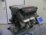
Mechanical engineers design and build engines and power plants...

Mechanical engineers design and build engines and power plants...
...structures and vehicles of all sizes...

...structures and vehicles of all sizes...
...and moving mechanisms, machines, and robots.

...and moving mechanisms, machines, and robots.

[edit] Development

Mechanical engineering could be found in many ancient and medieval societies throughout the globe. In ancient Greece, the works of Archimedes (287 BC–212 BC), and Heron of Alexandria (10–70 AD) deeply influenced mechanics in the Western tradition. In ancient China, there were also many notable figures, such as Zhang Heng (78–139 AD) and Ma Jun (200–265 AD). The medieval Chinese horologist and engineer Su Song (1020–1101 AD) incorporated an escapement mechanism into his astronomical clock tower two centuries before any escapement could be found in clocks of medieval Europe, as well as the world's first known endless power-transmitting chain drive.[1]

During the early 19th century in Britain, the development of machine-tools led mechanical engineering to develop as a separate field within engineering, providing manufacturing machines and the engines to power them.[2] The first British professional society of mechanical engineers was formed in 1847, making mechanical engineering the second-oldest branch of engineering behind civil, formed 30 years earlier.[3] In the United States, the first mechanical engineering professional society was formed in 1880, making it the third oldest type of engineering behind civil (1852) and mining & metallurgical (1871).[4] The first schools in the United States to offer an engineering education were the United States Military Academy in 1817, an institution now known as Norwich University in 1819, and Rensselaer Polytechnic Institute in 1825. Education in mechanical engineering has historically been based on a strong foundation in mathematics and science; this is followed by courses emphasizing the application of this knowledge and studies in the social sciences and humanities to give the engineer a broader education.[5]

[edit] Education

Degrees in mechanical engineering are offered at universities in most industrialized nations. In China, India, North America and elsewhere, mechanical engineering programs typically take 4 to 5 years and result in a Bachelor of Science (BSc), Bachelor of Technology (BTech), Bachelor of Engineering (B.E), or a Bachelor of Applied Science (B.A.Sc.) with emphasis in mechanical engineering. In Spain, Portugal and most of South America where the (BSc) or (BTech) programs have not been adopted, the formal name for the degree is "Mechanical Engineer" and the course work is based on 5–6 years of training.

In the U.S., most undergraduate Mechanical Engineering programs are accredited by the Accreditation Board for Engineering and Technology (ABET) to ensure similar course requirements and standards between universities. The ABET web site lists 276 accredited Mechanical Engineering programs as of June 19, 2006.[6] Mechanical Engineering programs in Canada are accredited by the Canadian Engineering Accreditation Board (CEAB),[7] and most other countries offering engineering degrees have similar accreditation societies.

Some Mechanical Engineers go on to pursue a postgraduate degree such as a Master of Engineering, Master of Science, Master of Engineering Management (MEng.Mgt, MEM), a Doctor of Philosophy in Engineering (EngD, PhD) or an Engineer's degree. The Master's and Engineer's degrees may consist of either research, coursework or a mixture of the two. The Doctor of Philosophy consists of a significant research component and is often viewed as the entry point to academia.[8]

[edit] Coursework

Mechanical engineering programs generally cover the same fundamental subjects, to meet standards set by each country's accreditation society. Engineering programs in the U.S., for instance, are required by ABET to show that their students can "work professionally in both thermal and mechanical systems areas."[9] This is to ensure a minimum level of competence among graduating engineers and to inspire confidence in the engineering profession as a whole. The specific courses required to graduate, however, may differ from program to program. Universities will often combine multiple subjects into a single class or split a subject into multiple classes, depending on the faculty available and the university's major area(s) of research. Fundamental subjects of mechanical engineering usually include:

Mechanical engineers are also expected to understand and be able to apply basic concepts from chemistry, chemical engineering, electrical engineering, civil engineering, and physics. Most mechanical engineering programs include several semesters of calculus, as well as advanced mathematical concepts which may include differential equations and partial differential equations, linear and modern algebra, and differential geometry, among others.

In addition to the core mechanical engineering curriculum, many mechanical engineering programs offer more specialized programs and classes, such as mechatronics / robotics, transport and logistics, cryogenics, fuel technology, automotive engineering, biomechanics, vibration, optics and others, if a separate department does not exist for these subjects.[12]

Most mechanical engineering programs also require varying amounts of research or community projects to gain practical problem-solving experience. Mechanical engineering students usually hold one or more internships while studying, though this is not typically mandated by the university.

[edit] License

Engineers may seek license by a state, provincial, or national government. The purpose of this process is to ensure that engineers possess the necessary technical knowledge, real-world experience, and knowledge of the local legal system to practice engineering at a professional level. Once certified, the engineer is given the title of Professional Engineer (in the United States, Canada, Japan, South Korea and South Africa), Chartered Engineer (in the UK, Ireland, India and Zimbabwe), Chartered Professional Engineer (in Australia and New Zealand) or European Engineer (much of the European Union). Not all mechanical engineers choose to become licensed; those that do can be distinguished as Chartered or Professional Engineers by the post-nominal title P.E., P. Eng., or C.Eng., as in: Ryan Jones, P.Eng.

In the U.S., to become a licensed Professional Engineer, an Engineer must pass the comprehensive FE (Fundamentals of Engineering) exam, work a given number of years as an Engineering Intern (EI) or Engineer-in-Training (EIT), and finally pass the "Principles and Practice" or PE (Practicing Engineer or Professional Engineer) exam.

In the United States, the requirements and steps of this process are set forth by the National Council of Examiners for Engineering and Surveying (NCEES), a national non-profit representing all states. In the UK, current graduates require a MSc, MEng or BEng (Hons) in order to become chartered through the Institution of Mechanical Engineers.

In most modern countries, certain engineering tasks, such as the design of bridges, electric power plants, and chemical plants, must be approved by a Professional Engineer or a Chartered Engineer. "Only a licensed engineer, for instance, may prepare, sign, seal and submit engineering plans and drawings to an public authority for approval, or to seal engineering work for public and private clients."[13] This requirement can be written into state and provincial legislation, such as Quebec's Engineer Act.[14] In other countries, such as Australia, no such legislation exists; however, practically all certifying bodies maintain a code of ethics independent of legislation that they expect all members to abide by or risk expulsion.[15]

Further information: FE Exam, Professional Engineer, Chartered Engineer, Incorporated Engineer, and Washington Accord

[edit] Salaries and workforce statistics

The total number of engineers employed in the U.S. in 2004 was roughly 1.4 million. Of these, 226,000 were mechanical engineers (15.6%), second only to civil engineers in size at 237,000 (16.4%). The total number of mechanical engineering jobs in 2004 was projected to grow 9 to 17%, with average starting salaries being $50,236 with a bachelor's degree, $59,880 with a master's degree, and $68,299 with a doctorate degree. This places mechanical engineering at 8th of 14 among engineering bachelors degrees, 4th of 11 among masters degrees, and 6th of 7 among doctorate degrees in average annual salary.[16] The median annual earning of mechanical engineers in the U.S. workforce is roughly $63,000. This number is highest when working for the government ($72,500), and lowest when doing general purpose machinery manufacturing in the private sector ($55,850).[17]

Canadian engineers make an average of $29.83 per hour with 4% unemployed. The average for all occupations is $18.07 per hour with 7% unemployed. Twelve percent of these engineers are self-employed, and since 1997 the proportion of female engineers has risen to 6%.[18]

[edit] Modern Tools

Many mechanical engineering companies, especially those in industrialized nations, have begun to incorporate Computer-aided engineering (CAE) programs into their existing design and analysis processes. For instance, companies may use Computer-aided design (CAD) for design of products in 2D and 3D. This method has many benefits, including easier and more exhaustive visualization of products, the ability to create virtual assemblies of parts, and the ease of use in designing mating interfaces and tolerances.

Other CAE programs commonly used by mechanical engineers include product lifecycle management(PLM) tools and analysis tools used to perform complex simulations. Analysis tools may be used to predict product response to expected loads, including fatigue life and manufacturability. These tools include Finite element analysis (FEA), Computational fluid dynamics (CFD), and Computer-aided manufacturing (CAM).

Using CAE programs, a mechanical design team can quickly and cheaply iterate the design process to develop a product that better meets cost, performance, and other constraints. No physical prototype need be created until the design nears completion, allowing hundreds or thousands of designs to be evaluated, instead of a relative few. In addition, CAE analysis programs can model complicated physical phenomena which cannot be solved by hand, such as viscoelasticity, complex contact between mating parts, or non-Newtonian flows

As mechanical engineering begins to merge with other disciplines, as seen in mechatronics, Multidisciplinary design optimization (MDO) is being used with other CAE programs to automate and improve the iterative design process. MDO tools wrap around existing CAE processes, allowing product evaluation to continue even after the analyst goes home for the day. They also utilize sophisticated optimization algorithms to more intelligently explore possible designs, often finding better, innovative solutions to difficult multidisciplinary design problems.

[edit] Subdisciplines

The field of mechanical engineering can be thought of as a collection of many mechanical disciplines. Several of these subdisciplines which are typically taught at the undergraduate level are listed below, with a brief explanation and the most common application of each. Some of these subdisciplines are unique to mechanical engineering, while others are a combination of mechanical engineering and one or more other disciplines. Most work that a mechanical engineer does uses skills and techniques from several of these subdisciplines, as well as specialized subdisciplines. Specialized subdisciplines, as used in this article, are usually the subject of graduate studies or on-the-job training more than undergraduate research. Several specialized subdisciplines are discussed at the end of this section.

[


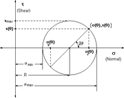
Mohr's circle, a common tool to study stresses in a mechanical element

Mohr's circle, a common tool to study stresses in a mechanical element

Mechanics is, in the most general sense, the study of forces and their effect upon matter. Typically, engineering mechanics is used to analyze and predict the acceleration and deformation (both elastic and plastic) of objects under known forces (also called loads) or stresses. Subdisciplines of mechanics include

Mechanical engineers typically use mechanics in the design or analysis phases of engineering. If the engineering project were the design of a vehicle, statics might be employed to design the frame of the vehicle, in order to evaluate where the stresses will be most intense. Dynamics might be used when designing the car's engine, to evaluate the forces in the pistons and cams as the engine cycles. Mechanics of materials might be used to choose appropriate materials for the frame and engine. Fluid mechanics might be used to design a ventilation system for the vehicle (see HVAC), or to design the intake system for the engine.

[edit] Kinematics

Main article: Kinematics

Kinematics is the study of the motion of bodies (objects) and systems (groups of objects), while ignoring the forces that cause the motion. The movement of a crane and the oscillations of a piston in an engine are both simple kinematic systems. The crane is a type of open kinematic chain, while the piston is part of a closed four bar linkage.

Mechanical engineers typically use kinematics in the design and analysis of mechanisms. Kinematics can be used to find the possible range of motion for a given mechanism, or, working in reverse, can be used to design a mechanism that has a desired range of motion.

[edit] Mechatronics and robotics

Main article: Mechatronics
Main article: Robotics

Mechatronics is an interdisciplinary branch of mechanical engineering, electrical engineering and software engineering that is concerned with integrating electrical and mechanical engineering to create hybrid systems. In this way, machines can be automated through the use of electric motors, servo-mechanisms, and other electrical systems in conjunction with special software. A common example of a mechatronics system is a CD-ROM drive. Mechanical systems open and close the drive, spin the CD and move the laser, while an optical system reads the data on the CD and converts it to bits. Integrated software controls the process and communicates the contents of the CD to the computer.

Mechatronics is currently used in the following areas of engineering, among others:

Industrial robots perform repetitive tasks, such as assembling vehicles.

Industrial robots perform repetitive tasks, such as assembling vehicles.

Robotics is the application of mechatronics to create robots, which perform tasks that are dangerous, unpleasant, or repetitive. These robots may be of any shape and size, but all are preprogrammed and interact physically with the world. To create a robot, an engineer typically employs kinematics (to determine the robot's range of motion) and mechanics (to determine the stresses within the robot).

Robots are used extensively in Industrial engineering. They allow businesses to save money on labor and perform tasks that are either too dangerous or too precise for humans to perform them economically. Many companies employ assembly lines of robots, and some factories are so robotized that they can run by themselves. Outside the factory, robots have been employed in bomb disposal, space exploration, and many other fields. Robots are also sold for various residential applications.

[edit] Structural analysis

Main article: Structural analysis
Main article: Failure analysis

Structural analysis is the branch of mechanical engineering (and also civil engineering) devoted to examining why and how objects fail. Structural failures occur in two general modes: static failure, and fatigue failure. Static structural failure occurs when, upon being loaded (having a force applied) the object being analyzed either breaks or is deformed plastically, depending on the criterion for failure. Fatigue failure occurs when an object fails after a number of repeated loading and unloading cycles. Fatigue failure occurs because of imperfections in the object: a microscopic crack on the surface of the object, for instance, will grow slightly with each cycle (propagation) until the crack is large enough to cause ultimate failure.

Failure is not simply defined as when a part breaks, however; it is defined as when a part does not operate as intended. Some systems, such as the perforated top sections of some plastic bags, are designed to break. If these systems do not break, failure analysis might be employed to determine the cause.

Structural analysis is often used by mechanical engineers after a failure has occurred, or when designing to prevent failure. Engineers may use various books and handbooks such as those published by ASM[20] to aid them in determining the type of failure and possible causes.

Structural analysis may be used in the office when designing parts, in the field to analyze failed parts, or in laboratories where parts might undergo controlled failure tests.


Thermodynamics is an applied science used in several branches of engineering, including Mechanical and Chemical Engineering. At its simplest, thermodynamics is the study of energy, its use and transformation through a system. Typically, engineering thermodynamics is concerned with changing energy from one form to another. As an example, automotive engines convert chemical energy (enthalpy) from the fuel into heat, and then into mechanical work that eventually turns the wheels.

Thermodynamics principles are used by mechanical engineers in the fields of heat transfer, thermofluids, and energy conversion. Mechanical engineers use thermo-science to design engines and power plants, heating, ventilation, and air-conditioning (HVAC) systems, heat exchangers, heat sinks, radiators, refrigeration, insulation, and others.

[edit] Drafting

A CAD model of a mechanical double seal

A CAD model of a mechanical double seal
Main article: Technical drawing
Main article: CNC

Drafting or technical drawing is the means by which mechanical engineers create instructions for manufacturing parts. A technical drawing can be a computer model or hand-drawn schematic showing all the dimensions necessary to manufacture a part, as well as assembly notes, a list of required materials, and other pertinent information. A U.S. mechanical engineer or skilled worker who creates technical drawings may be referred to as a drafter or draftsman (or, in a more politically correct way, draftsperson). Drafting has historically been a two-dimensional process, but recent Computer-Aided Designing (CAD) programs have begun to allow the designer to create in three dimensions.

Instructions for manufacturing a part must be fed to the necessary machinery, either manually, through programmed instructions, or through the use of a Computer-Aided Manufacturing (CAM) or combined CAD/CAM program. Optionally, an engineer may also manually manufacture a part using the technical drawings, but this is becoming an increasing rarity, with the advent of CNC (Computer Numerically Controlled) manufacturing. Engineers primarily manually manufacture parts in the areas of applied spray coatings, finishes, and other processes that cannot economically or practically be done by a machine.

Drafting is used in nearly every subdiscipline of mechanical engineering, and by many other branches of engineering and architecture. Three-dimensional models created using CAD software are also commonly used in Finite element analysis (FEA) and Computational fluid dynamics (CFD).

[edit] Specialized subdisciplines

An aerodynamic test vehicle used by mechanical engineers.

An aerodynamic test vehicle used by mechanical engineers.

The following is a list of some additional subdisciplines and topics within mechanical engineering. These topics may be considered specialized because they are not typically part of undergraduate mechanical engineering requirements, or require training beyond an undergraduate level to be useful.


[edit] Frontiers of research

Mechanical engineers are constantly pushing the boundaries of what is physically possible in order to produce safer, cheaper, and more efficient machines and mechanical systems. Some technologies at the cutting edge of mechanical engineering are listed below (see also exploratory engineering).

[edit] Composites

Composite cloth consisting of woven carbon fiber.

Composite cloth consisting of woven carbon fiber.
Main article: Composite material

Composites or composite materials are a combination of materials which provide different physical characteristics than either material separately. Composite material research within mechanical engineering typically focuses on designing (and, subsequently, finding applications for) stronger or more rigid materials while attempting to reduce weight, suceptability to corrosion, and other undesirable factors. Carbon fiber reinforced composites, for instance, have been used in such diverse applications as spacecraft and fishing rods.

[edit] Mechatronics

Main article: Mechatronics

Mechatronics is the synergistic combination of mechanical engineering, electronic engineering, and software engineering. The purpose of this interdisciplinary engineering field is the study of automata from an engineering perspective and serves the purposes of controlling advanced hybrid systems.

[edit] Nanotechnology

Main article: Nanotechnology

At the smallest scales, mechanical engineering becomes nanotechnology and molecular engineering—one speculative goal of which is to create a molecular assembler to build molecules and materials via mechanosynthesis. For now this goal remains within exploratory engineering.

歡迎來到Bewise Inc.的世界,首先恭喜您來到這接受新的資訊讓產業更有競爭力,我們是提供專業刀具製造商,應對客戶高品質的刀具需求,我們可以協助客戶滿足您對產業的不同要求,我們有能力達到非常卓越的客戶需求品質,這是現有相關技術無法比擬的,我們成功的滿足了各行各業的要求,包括:精密HSS DIN切削刀具協助客戶設計刀具流程DIN or JIS 鎢鋼切削刀具設計NAS986 NAS965 NAS897 NAS937orNAS907 航太切削刀具,NAS航太刀具設計超高硬度的切削刀具BW捨棄式鑽石V卡刀BW捨棄式金屬圓鋸片木工捨棄式金屬圓鋸片PCD木工圓鋸片醫療配件刀具設計汽車業刀具設計

beeway 發表在 痞客邦 留言(0) 人氣()


Bewise Inc. www.tool-tool.com Reference source from the internet.

A modern CNC machine can perform most machining operations with high precision.

A modern CNC machine can perform most machining operations with high precision.

Conventional machining, one of the most important material removal methods, is a collection of material-working processes in which power-driven machine tools, such as lathes, milling machines, and drill presses are used with a sharp cutting tool to mechanically cut the material to achieve the desired geometry. Machining is a part of the manufacture of almost all metal products. It is not uncommon for other materials to be machined. A person who specializes in machining is called a machinist. Machining is also a hobby. A room, building, or company where machining is done is called a machine shop.

[edit] Machining operations

The three principal machining processes are classified as turning, drilling and milling. Other operations falling into miscellaneous categories include shaping, planing, broaching and sawing. Turning operations are operations that rotate the workpiece as the primary method of moving metal against the cutting tool. Lathes are the principal machine tool used in turning. Milling operations are operations in which the cutting tool rotates to bring cutting edges to bear against the workpiece. Milling machines are the principal machine tool used in milling. Drilling operations are operations in which holes are produced or refined by bringing a rotating cutter with cutting edges at the lower extremity into contact with the workpiece. Drilling operations are done primarily in drill presses but not uncommon on the lathes or mills. Miscellaneous operations are operations that strictly speaking may not be machining operations in that they may not be chip producing operations but these operations are performed at a typical machine tool. Burnishing is an example of a miscellaneous operation. Burnishing produces no chips but can be performed at a lathe, mill, or drill press.

An unfinished workpiece requiring machining will need to have some material cut away to create a finished product. A finished product would be a workpiece that meets the specifications set out for that workpiece by engineering drawings or blueprints. For example, a workpiece may be required to have a specific outside diameter. A lathe is a machine tool that can be used to create that diameter by rotating a metal workpiece, so that a cutting tool can cut metal away, creating a smooth, round surface matching the required diameter and surface finish. A drill can be used to remove metal in the shape of a cylindrical hole. Other tools that may be used for various types of metal removal are milling machines, saws, and grinding tools. Many of these same techniques are used in woodworking.

More recent, advanced machining techniques include electrical discharge machining (EDM), electro-chemical erosion, laser, or water jet cutting to shape metal workpieces.

As a commercial venture, machining is generally performed in a machine shop, which consists of one or more workrooms containing major machine tools. Although a machine shop can be a stand alone operation, many businesses maintain internal machine shops which support specialized needs of the business.

Machining requires attention to many details for a workpiece to meet the specifications set out in the engineering drawings or blueprints. Beside the obvious problems related to correct dimensions, there is the problem of achieving the correct finish or surface smoothness on the workpiece. The inferior finish found on the machined surface of a workpiece may be caused by incorrect clamping, dull tool, or inappropriate presentation of a tool. Frequently, this poor surface finish, known as chatter, is evident by an undulating or irregular finish, and the appearance of waves on the machined surfaces of the workpiece.

Basic machining process.

Basic machining process.

[edit] Overview of machining technology

Machining is not just one process; it is a group of processes. The common feature is the use of a cutting tool to form a chip that is removed from the workpart. To perform the operation, relative motion is required between the tool and work. This relative motion is achieved in most machining operation by means of a primary motion, called cutting speed and a secondary motion called feed. The shape of the tool and its penetration into the work surface, combined with these motions, produce the desired shape of the resulting work surface.

[edit] Types of machining operation

There are many kinds of machining operations, each of which is capable of generating a certain part geometry and surface texture.

In turning, a cutting tool with a single cutting edge is used to remove material from a rotating workpiece to generate a cylindrical shape. The speed motion in turning is provided by the rotating workpart, and the feed motion is achieved by the cutting tool moving slowly in a direction parallel to the axis of rotation of the workpiece.

Drilling is used to create a round hole. It is accomplished by a rotating tool that is typically has two cutting edges. The tool is fed in a direction parallel to its axis of rotation into the workpart to form the round hole.

In boring, the tool is used to enlarge an already available hole. It is a fine finishing operation used in the final stages of product manufacture.

In milling, a rotating tool with multiple cutting edges is moved slowly relative to the material to generate a plane or straight surface. The direction of the feed motion is perpendicular to the tool's axis of rotation. The speed motion is provided by the rotating milling cutter. The two basic forms of milling are —

Peripheral milling
Face milling

Other conventional machining operations include shaping, planing, broaching and sawing. Also, grinding and similar abrasive operations are often included within the category of machining.

[edit] The cutting tool

A cutting tool has one or more sharp cutting edgesand is made of a material that harder than the work material. The cutting edge serves to separate chip from the parent work material. Connected to the cutting edge are the two surfaces of the tool —

The rake face; and
The flank.

The rake face which directs the flow of newly formed chip, is oriented at a certain angle is called the rake angle "α". It is measured relative to the plane perpendicular to the work surface. The rake angle can be positive or negative. The flank of the tool provides a clearance between the tool and the newly formed work surface, thus protecting the surface from abrasion, which would degrade the finish. This angle between the work surface and the flank surface is called the relief angle. There are two basic types of cutting tools —

  1. Single point tool; and
  2. Multiple-cutting-edge tool.

A single point tool has one cutting edge and is used for turning. During mechining, the point of the penetrates below the original work surface of the workpart. The point is usily rounded to a certain radius, called the nose radius.

Multiple-cutting-edge tools have more than one cutting edge and usually achieve their motion relative to the workpartby rotating. Drilling and milling uses rotating multiple-cutting-edge tools. Although the shapes of these tools are different from a single-point tool, many elements of tool geometry are similar.

[edit] Cutting conditions

Relative motion is required between the tool and work to perform a machining operation. The primary motion is accomplished at a certain cutting speed. In addition, the tool must be moved laterally across the work. This is a much slower motion, called the feed. The remaining dimension of the cut is the penetration of the cutting tool below the original work surface, called the depth of cut. Collectively, speed, feed, and depth of cut are called the cutting conditions. They form the three dimensions of the machining process, and for certain operations, their product can be used to obtain the material removal rate for the process —

{R}_{MR} = vfd\,\!

where —

  • {R}_{MR}\,\! — the material removal rate in mm3/s, (in3/s),
  • v\,\! — the cutting speed in m/s, (ft/min),
  • f\,\! — the feed in mm, (in),
  • d\,\! — the depth of cut in mm, (in).


Note:— All units MUST be converted to the corresponding decimal (or USCU) units.

Machining operations usually divide into two categories, distinguished by purpose and cutting conditions:

Roughing cuts, and
Finishing cuts.

Roughing cuts are used to remove large amount of material from the starting workpart as rapidly as possible, in order to produce a shape close to the desired form, but leaving some material on the piece for a subsequent finishing operation. Finishing cuts are used to complete the part and achieve the final dimension, tolerances, and surface finish. In production machining jobs, one or more roughing cuts are usually performed on the work, followed by one or two finishing cuts. Roughing operations are done at high feeds and depths — feeds of .04-1.25 mm/rev (0.015-0.050 in/rev) and depths of 2.5-20 mm (0.100-0.750 in) are typical. Finishing operations are carried out at low feeds and depths - feeds of 0.0125-0.04 mm/rev (0.0005-0.0015 in/rev) and depths of 0.75-2.0 mm (0.030-0.075 in) are typical. Cutting speeds are lower in roughing than in finishing.

A cutting fluid is often applied to the machining operation to cool and lubricate the cutting tool. Determining whether a cutting fluid should be used, and, if so, choosing the proper cutting fluid, is usually included within the scope of cutting condition.

[edit] Stages in metal cutting

Roughing cuts are used to remove large amount of material from the starting workpart as rapidly as possible, in order to produce a shape close to the desired form, but leaving some material on the piece for a subsequent finishing operation. Finishing cuts are used to complete the part and achieve the final dimension, tolerances, and surface finish. In production machining jobs, one or more roughing cuts are usually performed on the work, followed by one or two finishing cuts. Roughing operations are done at high feeds and depths — feeds of .04-1.25 mm/rev (0.015-0.050 in/rev) and depths of 2.5-20 mm (0.100-0.750 in) are typical. Finishing operations are carried out at low feeds and depths - feeds of 0.125-0.4 mm/rev (0.005-0.015 in/rev) and depths of 0.75-2.0 mm (0.030-0.075 in) are typical. Cutting speeds are lower in roughing than in finishing.

A cutting fluid is often applied to the machining operation to cool and lubricate the cutting tool. Determining whether a cutting fluid should be used, and, if so, choosing the proper cutting fluid, is usually included within the scope of cutting condition.

歡迎來到Bewise Inc.的世界,首先恭喜您來到這接受新的資訊讓產業更有競爭力,我們是提供專業刀具製造商,應對客戶高品質的刀具需求,我們可以協助客戶滿足您對產業的不同要求,我們有能力達到非常卓越的客戶需求品質,這是現有相關技術無法比擬的,我們成功的滿足了各行各業的要求,包括:精密HSS DIN切削刀具協助客戶設計刀具流程DIN or JIS 鎢鋼切削刀具設計NAS986 NAS965 NAS897 NAS937orNAS907 航太切削刀具,NAS航太刀具設計超高硬度的切削刀具BW捨棄式鑽石V卡刀BW捨棄式金屬圓鋸片木工捨棄式金屬圓鋸片PCD木工圓鋸片醫療配件刀具設計汽車業刀具設計電子產業鑽石刀具全鎢鋼V卡刀-電路版專用全鎢鋼鋸片焊刃式側銑刀焊刃式千鳥側銑刀焊刃式T型銑刀焊刃式千鳥T型銑刀焊刃式螺旋機械鉸刀全鎢鋼斜邊刀電路版專用鎢鋼焊刃式高速鉸刀超微粒鎢鋼機械鉸刀超微粒鎢鋼定點鑽焊刃式帶柄角度銑刀焊刃式螺旋立銑刀焊刃式帶柄倒角銑刀焊刃式角度銑刀焊刃式筒型平面銑刀木工產業鑽石刀具等等。我們的產品涵蓋了從民生刀具到工業級的刀具設計;從微細刀具到大型刀具;從小型生產到大型量產;全自動整合;我們的技術可提供您連續生產的效能,我們整體的服務及卓越的技術,恭迎您親自體驗!!

BW Bewise Inc. Willy Chen willy@tool-tool.com bw@tool-tool.com www.tool-tool.com skype:willy_chen_bw mobile:0937-618-190 Head &Administration Office No.13,Shiang Shang 2nd St., West Chiu Taichung,Taiwan 40356 http://www.tool-tool..com / FAX:+886 4 2471 4839 N.Branch 5F,No.460,Fu Shin North Rd.,Taipei,Taiwan S.Branch No.24,Sec.1,Chia Pu East Rd.,Taipao City,Chiayi Hsien,Taiwan

Welcome to BW tool world! We are an experienced tool maker specialized in cutting tools. We focus on what you need and endeavor to research the best cutter to satisfy users demand. Our customers involve wide range of industries, like mold & die, aerospace, electronic, machinery, etc. We are professional expert in cutting field. We would like to solve every problem from you. Please feel free to contact us, its our pleasure to serve for you. BW product including: cutting toolaerospace tool .HSS DIN Cutting toolCarbide end millsCarbide cutting toolNAS Cutting toolNAS986 NAS965 NAS897 NAS937orNAS907 Cutting Tools,Carbide end milldisc milling cutter,Aerospace cutting toolhss drillФрезерыCarbide drillHigh speed steelMilling cutterCVDD(Chemical Vapor Deposition Diamond )’PCBN (Polycrystalline Cubic Boron Nitride) Core drillTapered end millsCVD Diamond Tools Inserts’PCD Edge-Beveling Cutter(Golden FingerEdge modifying knifeSolid carbide saw blade-V typeV-type locking-special use for PC boardMetal Slitting SawaCarbide Side milling CuttersCarbide Side Milling Cutters With Staggered TeethCarbide T-Slot Milling CuttersCarbide T-Slot Milling Cutters With Staggered TeethCarbide Machine ReamersHigh speed reamer-standard typeHigh speed reamer-long type’’PCD V-CutterPCD Wood toolsPCD Cutting toolsPCD Circular Saw BladePVDD End Millsdiamond tool V-type locking-special use for PC board Single Crystal Diamond Metric end millsMiniature end millsСпециальные режущие инструменты Пустотелое сверло Pilot reamerFraisesFresas con mango PCD (Polycrystalline diamond) ‘FreseElectronics cutterStep drillMetal cutting sawDouble margin drillGun barrelAngle milling cutterCarbide burrsCarbide tipped cutterChamfering toolIC card engraving cutterSide cutterNAS toolDIN or JIS toolSpecial toolMetal slitting sawsShell end millsSide and face milling cuttersSide chip clearance sawsLong end millsStub roughing end millsDovetail milling cuttersCarbide slot drillsCarbide torus cuttersAngel carbide end millsCarbide torus cuttersCarbide ball-nosed slot drillsMould cutterTool manufacturer.

Bewise Inc. www.tool-tool.com

ようこそBewise Inc.の世界へお越し下さいませ、先ず御目出度たいのは新たな

情報を受け取って頂き、もっと各産業に競争力プラス展開。

弊社は専門なエンドミルの製造メーカーで、客先に色んな分野のニーズ

豊富なパリエーションを満足させ、特にハイテク

beeway 發表在 痞客邦 留言(0) 人氣()


Bewise Inc. www.tool-tool.com Reference source from the internet.

ECM is a method of removing metal by an electrochemical process. It is used for working extremely hard materials or materials that are difficult to machine using conventional methods. Its use is limited to electrically conductive materials; however, this includes all metals. ECM can cut small or odd-shaped angles, intricate contours or cavities in extremely hard steel and exotic metals such as titanium, hastelloy, kovar, inconel and carbide.

ECM is similar in concept to Electrical discharge machining in that a high current is passed between an electrode and the part, through an electrolyte material removal process having a negatively charged electrode (cathode), a conductive fluid (electolyte), and a conductive workpeice (anode); however, in ECM there is no tool wear. The ECM cutting tool is guided along the desired path very close to the work but it does not touch the piece. Unlike EDM however, no sparks are created. The workpiece is eroded away in the reverse process to electroplating. Very high metal removal rates are possible with ECM, along with no thermal or mechanical stresses being transferred to the part, and mirror surface finishes are possible.

As far back as 1929, an experimental ECM process was developed by W.Gussef, although it took until 1959 for a commercial process to be established by the Anocut Engineering Company. Much research was done in the 1960s and 1970s, particularly in the gas turbine industry. The rise of EDM in the same period largely stopped research into ECM in the west, although work continued behind the Iron Curtain. The original problems of poor dimensional accuracy, and environmentally polluting waste have largely been overcome, although the process remains a niche technique. The cutting heads on all Philips 'Philishave' shavers are made using ECM.

The ECM process is most widely used to produce complicated shapes with good surface finish in difficult to machine materials, such as turbine blades. It is also widely and effectively used as a deburring process.

In the deburring process, the ECM uses techniques as described above to remove pieces of metal that are left over from the machining process, and to dull out sharp edges. This process is very fast and much more convenient than the conventional method of deburring by hand. It will tend to leave better surface finishing, and no metal deformation will occur because the tool piece doesn’t actually touch the metal.

歡迎來到Bewise Inc.的世界,首先恭喜您來到這接受新的資訊讓產業更有競爭力,我們是提供專業刀具製造商,應對客戶高品質的刀具需求,我們可以協助客戶滿足您對產業的不同要求,我們有能力達到非常卓越的客戶需求品質,這是現有相關技術無法比擬的,我們成功的滿足了各行各業的要求,包括:精密HSS DIN切削刀具協助客戶設計刀具流程DIN or JIS 鎢鋼切削刀具設計NAS986 NAS965 NAS897 NAS937orNAS907 航太切削刀具,NAS航太刀具設計超高硬度的切削刀具BW捨棄式鑽石V卡刀BW捨棄式金屬圓鋸片木工捨棄式金屬圓鋸片PCD木工圓鋸片醫療配件刀具設計汽車業刀具設計電子產業鑽石刀具全鎢鋼V卡刀-電路版專用全鎢鋼鋸片焊刃式側銑刀焊刃式千鳥側銑刀焊刃式T型銑刀焊刃式千鳥T型銑刀焊刃式螺旋機械鉸刀全鎢鋼斜邊刀電路版專用鎢鋼焊刃式高速鉸刀超微粒鎢鋼機械鉸刀超微粒鎢鋼定點鑽焊刃式帶柄角度銑刀焊刃式螺旋立銑刀焊刃式帶柄倒角銑刀焊刃式角度銑刀焊刃式筒型平面銑刀木工產業鑽石刀具等等。我們的產品涵蓋了從民生刀具到工業級的刀具設計;從微細刀具到大型刀具;從小型生產到大型量產;全自動整合;我們的技術可提供您連續生產的效能,我們整體的服務及卓越的技術,恭迎您親自體驗!!

BW Bewise Inc. Willy Chen willy@tool-tool.com bw@tool-tool.com www.tool-tool.com skype:willy_chen_bw mobile:0937-618-190 Head &Administration Office No.13,Shiang Shang 2nd St., West Chiu Taichung,Taiwan 40356 http://www.tool-tool..com / FAX:+886 4 2471 4839 N.Branch 5F,No.460,Fu Shin North Rd.,Taipei,Taiwan S.Branch No.24,Sec.1,Chia Pu East Rd.,Taipao City,Chiayi Hsien,Taiwan

Welcome to BW tool world! We are an experienced tool maker specialized in cutting tools. We focus on what you need and endeavor to research the best cutter to satisfy users demand. Our customers involve wide range of industries, like mold & die, aerospace, electronic, machinery, etc. We are professional expert in cutting field. We would like to solve every problem from you. Please feel free to contact us, its our pleasure to serve for you. BW product including: cutting toolaerospace tool .HSS DIN Cutting toolCarbide end millsCarbide cutting toolNAS Cutting toolNAS986 NAS965 NAS897 NAS937orNAS907 Cutting Tools,Carbide end milldisc milling cutter,Aerospace cutting toolhss drillФрезерыCarbide drillHigh speed steelMilling cutterCVDD(Chemical Vapor Deposition Diamond )’PCBN (Polycrystalline Cubic Boron Nitride) Core drillTapered end millsCVD Diamond Tools Inserts’PCD Edge-Beveling Cutter(Golden FingerEdge modifying knifeSolid carbide saw blade-V typeV-type locking-special use for PC boardMetal Slitting SawaCarbide Side milling CuttersCarbide Side Milling Cutters With Staggered TeethCarbide T-Slot Milling CuttersCarbide T-Slot Milling Cutters With Staggered TeethCarbide Machine ReamersHigh speed reamer-standard typeHigh speed reamer-long type’’PCD V-CutterPCD Wood toolsPCD Cutting toolsPCD Circular Saw BladePVDD End Millsdiamond tool V-type locking-special use for PC board Single Crystal Diamond Metric end millsMiniature end millsСпециальные режущие инструменты Пустотелое сверло Pilot reamerFraisesFresas con mango PCD (Polycrystalline diamond) ‘FreseElectronics cutterStep drillMetal cutting sawDouble margin drillGun barrelAngle milling cutterCarbide burrsCarbide tipped cutterChamfering toolIC card engraving cutterSide cutterNAS toolDIN or JIS toolSpecial toolMetal slitting sawsShell end millsSide and face milling cuttersSide chip clearance sawsLong end millsStub roughing end millsDovetail milling cuttersCarbide slot drillsCarbide torus cuttersAngel carbide end millsCarbide torus cuttersCarbide ball-nosed slot drillsMould cutterTool manufacturer.

Bewise Inc. www.tool-tool.com

ようこそBewise Inc.の世界へお越し下さいませ、先ず御目出度たいのは新たな

情報を受け取って頂き、もっと各産業に競争力プラス展開。

弊社は専門なエンドミルの製造メーカーで、客先に色んな分野のニーズ

豊富なパリエーションを満足させ、特にハイテク品質要求にサポート致します。

弊社は各領域に供給できる内容は:

(1)精密HSSエンドミルのR&D

(2)Carbide Cutting tools設計

(3)鎢鋼エンドミル設計

(4)航空エンドミル設計

(5)超高硬度エンドミル

(6)ダイヤモンドエンドミル

(7)医療用品エンドミル設計

(8)自動車部品&材料加工向けエンドミル設計

弊社の製品の供給調達機能は:

(1)生活産業~ハイテク工業までのエンドミル設計

(2)ミクロエンドミル~大型エンドミル供給

(3)小Lot生産~大量発注対応供給

(4)オートメーション整備調達

(5)スポット対応~流れ生産対応

弊社の全般供給体制及び技術自慢の総合専門製造メーカーに貴方のご体験を御待ちしております。

BW специализируется в научных исследованиях и разработках, и снабжаем самым высокотехнологичным карбидовым материалом для поставки режущих / фрезеровочных инструментов для почвы, воздушного пространства и электронной индустрии. В нашу основную продукцию входит твердый карбид / быстрорежущая сталь, а также двигатели, микроэлектрические дрели, IC картонорезальные машины, фрезы для гравирования, режущие пилы, фрезеры-расширители, фрезеры-расширители с резцом, дрели, резаки форм для шлицевого вала / звездочки роликовой цепи, и специальные нано инструменты. Пожалуйста, посетите сайт www.tool-tool.com для получения большей информации.

BW is specialized in R&D and sourcing the most advanced carbide material with high-tech coating to supply cutting / milling tool for mould & die, aero space and electronic industry. Our main products include solid carbide / HSS end mills, micro electronic drill, IC card cutter, engraving cutter, shell end mills, cutting saw, reamer, thread reamer, leading drill, involute gear cutter for spur wheel, rack and worm milling cutter, thread milling cutter, form cutters for spline shaft/roller chain sprocket, and special tool, with nano grade. Please visit our web www.tool-tool.com for more info.

beeway 發表在 痞客邦 留言(0) 人氣()